CMOS Circuits:
Before we go to CMOS circuits we should understand what is CMOS and how does it acts as a switch. Even before that let us learn NMOS and PMOS since complementary MOS (CMOS) constitute of NMOS FET and PMOS FET. Negative MOS FET (NMOS FET) illustrated in Figure (a) behaves as negative logic device and Positive MOS FET (PMOS FET) illustrated in Figure (b) behaves as positive logic device. Note down that the current direction for PMOS FET is into the transistor while it is out of the transistor for NMOS FET. The three terminals of a FET are termed as Source, Gate and Drain. Field Effect Transistor is a type of transistor and it is abbreviated as FET. A circuit diagram of CMOS is drawn in Figure (c), which is a combination of NMOS FET and PMOS FET. For our cause, we just have to understand the following two points on the operation of CMOS devices :
a) A Vcc input on the gate of NMOS FET will turn it on whereas it shall turn off the PMOS FET.
b) A 0 V input on the gate of NMOS FET shall turn it off while it will turn on the PMOS FET.
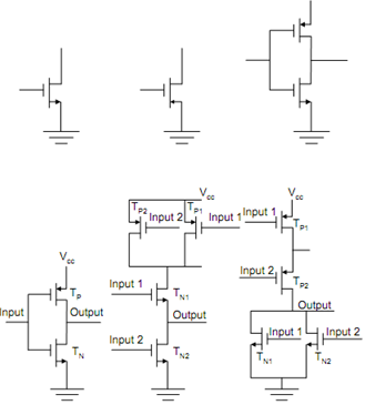
(d) (e) (f)
Figure: (a) NMOS FET, (b) PMOS FET, (c) CMOS FET, (d) CMOS NOT Gate, (e) CMOS NAND Gate, and (f) CMOS NOR Gate