Utility transformers:
A common core for the power transformer is E core, so named because it is shaped like capital letter E. A bar, placed at open end of E, completes the core once the coils have been wound on E-shaped section.
The primary and secondary windings can be placed on an E core in any of the two ways.
The simpler winding method is to put the primary and the secondary both around the middle bar of the E. This is known as shell method of transformer winding. It gives maximum coupling between the windings. However, shell winding scheme results in a considerable capacitance between the primary and the secondary. This capacitance can be tolerated sometimes; sometimes it cannot. Another disadvantage of shell geometry is that, when windings can be placed one atop the other, the transformer cannot handle large voltage.
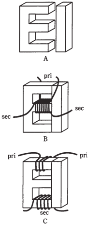
Figure-- Utility transformer E core (A), shell winding method (B), and core winding method (C).
Another winding method is core method. In this scheme, the primary is placed at the bottom of E section, and secondary can be placed at the top. The coupling occurs via magnetic flux in the core. The capacitance among the primary and secondary is much lower with this type of winding. A core wound transformer can handle higher voltages than the shell-wound transformer. At times the center part of the E is left out of the core when this winding scheme is used.
Shell wound and core wound transformers are universally employed at 60 Hz. These configurations are common at the audio frequencies.