Equivalent Circuit:
We may now develop the equivalent circuit of the transformer. The transformer windings contain some resistances and reactances. We may visualise the primary winding current to comprise two components as below.
(a) Exciting current I¯0 whose magnetising component I¯m creates mutual flux φ¯ and whose core loss component I¯i provides the loss associated with alternation of flux.
(b) A load component I¯2′ which counter balances the secondary magnetomotive force (mmf) I¯2 N2 so that the mutual flux remains constant independent of load.
Therefore, primary current I1 can be represented by
I¯1 = I¯0 + I¯2′
where
I2′ /I2 = N2 / N1
We will represent the primary winding/side quantities by subscript '1' and secondary by subscript '2'.
Thus, R1 and X1 are resistance and reactance of primary winding respectively and R2 and
X2 are resistance and reactance of secondary winding respectively.
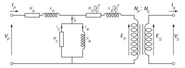
We may represent the transformers equivalent circuit as below illustrated in Figure.
We may also develop the equivalent circuit referred to either primary side or secondary.
Figure 5.3 : Equivalent Circuit of a Transformer Referred to Primary Side
Where X 2′ = X 2 ( N1/ N2)2
R 2′ = R 2 ( N1/ N2)2
V 2′ = V 2 ( N1/ N2)2
and
I 2′ = I 2 ( N1/ N2)2
Likewise we can represent the equivalent circuit referred to secondary side.
where
G i′ = ( N1/ N2)2 Gi
B i′ = ( N1/ N2)2 B i
R i′ = ( N1/ N2)2 R i
X i′ = ( N1/ N2)2 X i
V i′ = ( N1/ N2)2 V i
I i′ = ( N1/ N2)2 I i