The process for applying Thevenin’s theorem
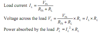
To find a current IL via the load resistance RL (as shown in figure below) by using Thevenin’s theorem, the following steps are as follows:
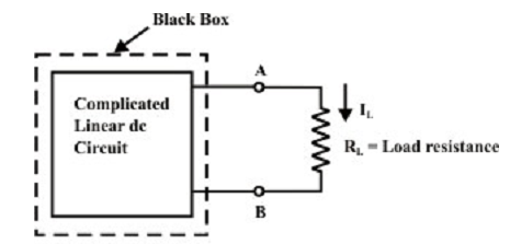
Step-1: Disconnect the load resistance (RL) from the circuit, as shown in figure.
Step-2: Compute the open-circuit voltage VTH (shown in figure above) at the load terminals (A and B) after disconnecting the load resistance (RL). In common, one can exert any of the methods (mesh-current, node-voltage and superposition technique) to calculate (experimentally just measure the voltage across the load terminals by using a voltmeter).
Step-3: Redraw the circuit (as shown in figure above) with each practical source substituted by its internal resistance as shown in figure below. Note that voltage sources must be short-circuited (just eliminate them and substitute with plain wire) and current sources must be open-circuited (just eliminated).
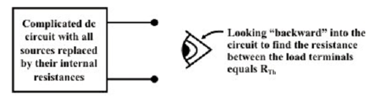
Step-4: Look backward into the resultant circuit from the load terminals (A & B), as recommended by the eye in figure above. Compute the resistance that would exist among the load terminals (or equivalently one can think as when a voltage source is exerted across the load terminals and then trace the current distribution via the circuit (as shown in figure above) in order to compute the resistance across the load terminals.) The resistance RTH is explained in the statement of Thevenin’s theorem. Once again, computing this resistance might be a hard task though one can try to use the standard circuit reduction method or Y-Δ or Δ-Y transformation methods.
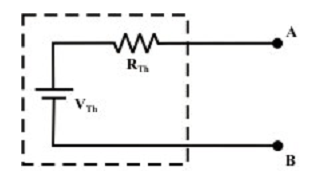
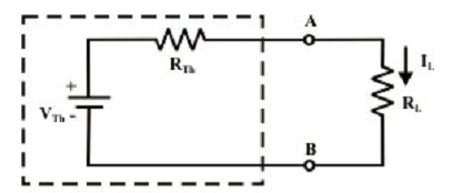
Step-5: Put RTH in series with VTH to form the Thevenin’s equivalent circuit (substituting the imaginary fencing section or fixed part of the circuit with an equivalent practical voltage source) as shown in figure above.
Step-6: Rejoin the original load to the Thevenin voltage circuit as shown in figure above; the load’s voltage, current and power might be computed by an easy arithmetic operation only.