Application of Thevenin’s theorem
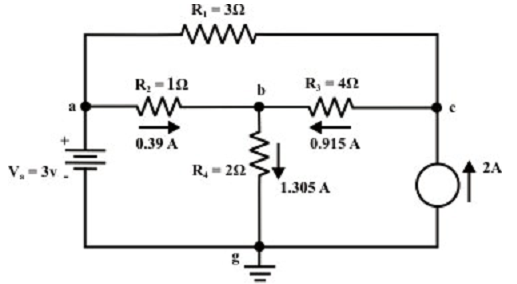
Example: For the circuit shown in figure below, find the current via RL = R2 = 1 Ω resistor (Ia-b branch) by using Thevenin’s theorem & therefore compute the voltage across the current source (Vcg).
Solution:
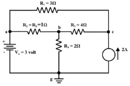
Step-1: Cut off the load resistance RL and redraw the circuit as shown in figure below.
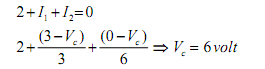
Step-2: Apply any technique (let say node-voltage technique) to compute VTH At node C:
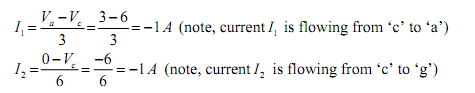
Now, the currents I1 and I2 can simply be calculated by using the following expressions.
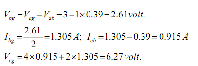
Step-3: Redraw the circuit (as shown above) pointing the direction of currents in various branches. One can find the Thevenin’s voltage by using the KVL around the closed path ‘gabg’ (as shown in figure below).
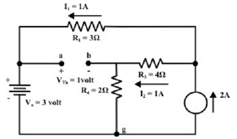
VTh=Vag – Vbg = 3-2 = 1 volt
Step-4: Substitute all sources by their internal resistances. In this trouble, voltage source having internal resistance zero (0) (i.e., ideal voltage source) and it is short-circuited with a wire. On the other hand, current source has an unlimited internal resistance (i.e., ideal current source) and it is open-circuited (just eliminate the current source). Thevenin’s resistance RTH of the fixed portion of the circuit can be calculated by looking at the load terminals ‘a’- ‘b’ (as shown in figure below).
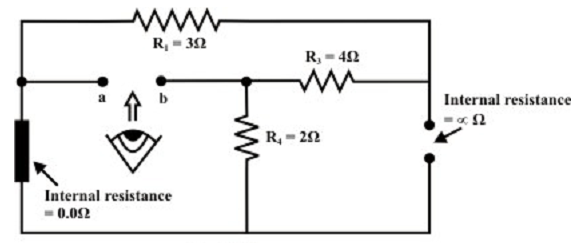
RTH = (R1 + R3) || R4 = (3+4) || 2 = 1.555 Ω
Step-5: Put RTH in series with VTH to form the Thevenin’s equivalent circuit (an easy practical voltage source). Rejoin the original load resistance RL = R2 = 1 Ω to the Thevenin’s equivalent circuit (note that the polarity of ‘a’ and ‘b’ is to be considered cautiously) as shown in figure below.
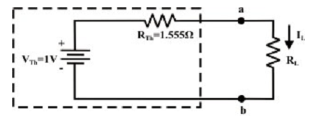
Step-6: The circuit is as shown in first figure is redrawn to point various branch currents. Referring to the figure shown below, one can compute the voltage Vbg and voltage across the current source (Vcg ) by using the equations shown below.