A Simple Tension Test
A tension test is a destructive test in the mean such the specimen is at last fractured or broken into pieces. For presenting a tension test one needs a machine able of applying load is to reason fracture. The testing machine will have proper holders or devices to hold the specimen hence a perfectly axial load is applied upon the test piece. The machine has to have device to measure the load at any facility and immediate for measurement of elongation of the test piece.
The specimen or test piece of the material is usually a straight piece; over the test length is uniform in the cross-section and often along with enlarged ends that can be held in the machine holders. However, Machines can hold specimen without particularly made or enlarged ends. Two fine marks are frequently made near the ends of uniform test section of the specimen or test piece and distance among the two points is termed "gauge length". The gauge length of a specimen or test piece bears a constant standardized ratio to the cross-sectional dimension for causes such will be discussed later.
The specimen or test piece is placed in the machine between the holders and any type of measuring device to record change in length is fitted onto the specimen or test piece among the gauge points. If that a device, often termed as "extensometer" is unfitted, the machine itself can record the distance among its cross-heads on that the specimen or test piece is held.
One time the machine is started this begins to apply a gradually increasing load on the specimen or test piece. At present intervals elongation of specimen and the reading of load are recorded. The raises in extension can be seemed from the specimen and like the extension begins to raises can be observed from the specimen and like the extension begins to increase at a faster rate or it can be judged from experience such extensometers if attached to specimen or test piece may be removed. Along with further raise in the load the extension raises at increased rate and record of extension might be acquired from displacement among the cross-heads. At several levels the load becomes stationary and the specimen or test piece either fails or begins to decrease in cross-section rapidly. The latter phenomenon is termed as necking and is followed by decreased in load accompanied via further extension till the specimen or test piece fractures into two pieces.
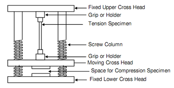
Figure: The Schematic Diagram of a Test Machine
The conclusions of tension test can be completely represented in form of a stress-strain diagram whether stress is strain as abscissa and plotted as ordinate. However, this may, be emphasized now that in the definition of stress; this is supposed that area of cross-section will not modify. It should have become clear through this time that throughout a tension test area of cross-section and length both modify considerably. Thus, there is a requirement to reconsider the definition of stress.
The stress is explained as ratio of load to original area of cross-section as denoted by A0. This will be explained as engineering stress. The prefix "engineering" is frequently dropped and whenever term stress is employed, this is understood that this is engineering stress. The ratio of load to definite or current area of cross-section is explained as true stress. The same, the ratio in the similar manner the true strain is the total of strains over minute ranges of load equal to the current load.
Engineering stress (σ) and strain (ε) will be:
σ = P/A0......................Eq(1)
ε = δL/L0......................Eq(2)
Here, P is load at any moment. A0 the original area of cross-section, δL, modify in length while load changed from zero to P and L0 is the original length.
Following diagrams show typical stress-strain figures for usual engineering materials. Figures for ductile materials are depicted in following figure, whilst Figure represents the same for brittle materials. These two sets have the similar strain scale and this can be represents that a ductile material represents considerable deformation before it fails whilst a brittle material represents little deformation. To differentiate between these two categories of material, materials along with strain less than 5 percent at fracture are considered as brittle and those having strains greater than 5 percent at fracture are named as ductile.
(a) Type A (b) Type B
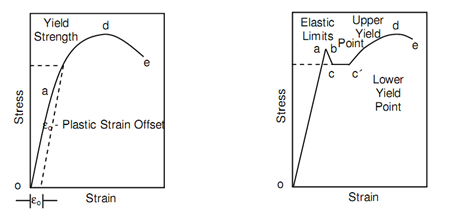
Figure: Stress-strain Diagram for Ductile Materials
The type A ductile materials in above figure (a)) comprise steels, copper alloys, aluminum alloys etc., whilst type B ductile materials are structural steel and mild steels. Distinguish among type A and type B ductile materials should be noted carefully. In both conditions the stress and strain be different linearly upto strain a. This area of deformation is elastic in the sense as if load is removed at any of point before reaching point a, the specimen or test piece will regain its original length and region of cross-section. Outside point a, ductile material of type A changes the connection that is more linear. Throughout this deformation, the strain modifies at a faster rate than stress, though this rate tends to reduces. Type B of ductile material represents distinctly distinguishes between behaviour than that represented in following figure (a). From a slightly higher point b in following figure (b), the stress drops unexpectedly to point c, keeps approximately constant over a range, then follows a pattern the same to that of type A.
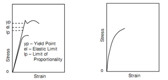
(a) Type A (b) Type B
Figure: Stress-strain Diagram for Brittle Materials
The unexpected drop in stress from b to c, raise in strain from c to c′ whilst stress keeps approximately constant is termed as "yielding". The point b from that the stress drops to point c, is termed as "upper yield point" whilst point c is termed as "lower yield point".
The deformation at approximately continuous stress is known as yield deformation.
One time a ductile material has gone beyond the elastic deformation it enters into plastic deformation range. The stress reaches maximum value at d, throughout this deformation, where necking in the specimen or test piece begins.
The stress at point d or the engineering stress is known as "Ultimate Tensile Strength" which is a very significant property. If loading is continuous, the specimen fails finally at e and stress decreased from point d to e. the stress at point e is termed as "fracture stress".
The deformation among point d and e in above previous figure is plastic is mean that if the specimen is unloaded at any point in between d and e the specimen will not recover its original size. In following figure shows the range of plastic and elastic deformations. The unloading of a specimen or test piece from any point f between a and d is specified in following figure. Unloading obeys a curve such is somewhat parallel to original elastic line. While specimen is completely unloaded to point g, several strains still keeps in it. It residual strain is the plastic component of strain by δp, a part of strain among f and g has been recovered and it is elastic part of strain at point f and indicated by εe. Hence, strain at point f,
εf = εfp + εfe..................................Eq(1)
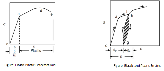
Upon reloading the specimen or test piece from point g, curve obeys a path extremely close to unloading curve and eventually joints the innovative curve at h. The region between unloading and loading curve as shown hatched in above figure shows the loss of energy because of unloading-cycle and is called as "hysteresis".
Type B brittle materials as demonstrated in previous figure of Stress-strain Diagram for Brittle Materials (b) do not represent linear relationship between strain and stress. Concrete is the illustration. The maximum stress sustained via such material is explained as final tensile strength. Type A brittle materials, similar to cast iron, will have also ultimate tensile strength and they represent linear relationship between ε and σ.