Stress
Stress given the intensity of a force -the quantity of force that acts on a unit area. The unit of stress will be N/mm2. If force acting over an area is uniformly distributed, stress can simply be determined as ratio of force to the area, which is:
Stress = Force/area……………1
In mostly practical cases the uniformly distributed forces are not present and therefore the stress is not uniform. Consequently, stress is usually referred to a point by considering an infinitesimally small area surrounding a point; hence, on this area uniform distribution of force can be assumed. It is a body the stress can vary from point to point excepting in such cases whereas the force is definitely distributed uniformly. One illustration of uniform stress distribution may be the cross-section of a tension specimen while axiality of tensile force is ensured. Force and area generally have three components in three-dimensional coordinate system. This is known that both force and area and vector quantities. Each has a magnitude and direction. The area has the direction of and normal or the area has two characteristics - area magnitude and its common, like force has two characteristics as- magnitude and direction. Thus the stress as defined in eqn. 1 will have three characteristics, namely:
• Magnitude, and
• Plane passing throughout the point on which stress acts,
• Direction whether stress is acting, which is the direction of the force
This common way of describing stress at a point that is often referred to as state of stress at a point, will be further taken-up at later stage.
In accordance with given diagram the stress may be classified as normal tensile or compressive, bearing or shear steels. The normal as compressive or tensile stress is produced over a section while force is acting normal to the section in given diagram (a). If the force is acting away from the section, the stress is tensile; if it is acting towards the section the stress is compressive. If the force P is uniformly distributed over the area A, the normal stress:
σ= P/A…………1
Τ= P/As …………3
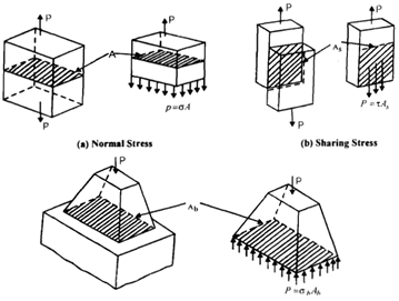
Diagram of: Two Types of Stresses at (a) and (b). Bearing Stress is similar Type as (a)Diagram of: Two Types Diagram (c) shows stress on two contacting surfaces named as bearing stress. This is basically pressure and acts like compression on two faces. This is a type of normal stress and compressive in nature. The average value of pressure or bearing stress is described by:
p = σb = P/Ab……………………4
Whereas Ab is the area of contact between the two bodies As an illustration consider a clevis carrying a load Pas shown in given diagram. The part A1 is subjected to a normal tensile stress. Part A2 is subjected also to normal tensile stress. The bolt cross-section is subjected to shearing stress where the inner surfaces of holes in part A2 and part A1 are subjected to bearing stress.
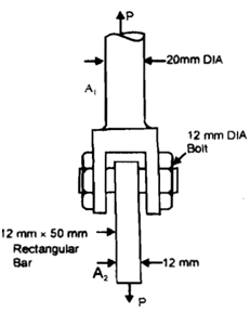
Diagram of : Clevis Supporting a Load P
Illustration
If the diameter of round part A1 is 200 millimeter and part A2 is 12 millimeter x 50 millimeter rectangular bar, determine tensile stress in both. If the diameter of bolt is 12 millimeter determine the shearing stress in bolt and bearing stress in bolt and bearing stress in the hole surface of part A2. P = 50 kN.
For determination of the bearing stress in the hole the area Ab may be taken as the projected area, whether this case will be equal to bolt diameter x thickness of A2.For determine shear stress it must be recognized that the bolt is beneath double shear and hence the area over which shear would happen is 2 x area of bolt cross-section.
Calculation of stress in part A1 or A2 of diagram will mean taking ratio of load to area of cross-section normal or transverse to the load. And because there will be no load in the plane of the cross-section normal to its axis, the stress at any point would be merely normal stress. Though, if a section is so chosen that it is not normal to the axis of part A2 given diagram, the stress then would not be normal. Such stress may be broken into two components - one normal and other shearing. Given below the diagram (b) shows that the force is not normal to the area hence normal stress likes that in eqn2 cannot be calculated. The force on oblique plane can be solved into two components - one perpendicular to oblique section (P cos?) and another parallel to oblique section (P sin q). The oblique section makes an angle qwith the normal cross-section. If the area of cross-section of the a part in below diagram (a) is A, then the area of the oblique plane is a/cosq and the component of force normal to the oblique plane is P cosq. Thus, the stress normal to oblique section is
σΘ = P/Acos2Θ = scos2Θ..........................5
Where s is the normal stress on transverse section
Likewise the force parallel to the oblique plane P sinq and hence the shearing stress on this plane is:
ΤΘ = (P/A)sinΘ = (s/2) sin2Θ.........................6
Obviously Θ = 0 defines the normal cross-section and for this plane cosΘ = 1, Plane cosΘ = 1 σΘ = P/A and ΤΘ = 0. Also it can be seen that t assumes a maximum value when Θ= 450
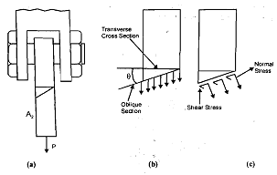
Diagram of: Stress on an Oblique Plane
Τmax = P/2A = σ/2.........................7
From preceding description this must become clear that the stress must be explained at a point in a body on a plane throughout the point. Hence it is imperative that the position of the point in the body and the configuration of the plane throughout that point be specified with the magnitude of the stress to explain the "state of stress" at a point in the body. This type of description of static of stress is generally accomplished by drawing a small rectangular element surrounding the point for two dimensional stresses and by drawing an elemental parallelepiped to represent three dimensional stresses. The edges of the rectangle or parallelepiped would represent the coordinates of reference and hence define the plane throughout the point of interest.
In below diagram (a) shows a three dimensional state of stress at a point and two dimensional or plane state of stress at a point is demonstrated by diagram (b). This can be seen that the element on whose faces the stresses are prescribed are clearly explained by the coordinate axes x, y and z or x and y. This will be worthwhile to describe the convention of naming the stresses at this stage or level.
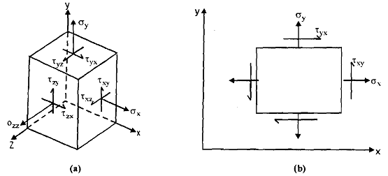
Diagram of: State of Stress at a point, (a) Three Dimensional; and (b) Plane
A direct or normal stress is denoted with letter s while a shearing stress with letter t. This may be remembered that a plane is described by its normal and thus x plane is one to which x-axis is normal. A stress, as has been stated earlier, should be defined by the plane on that it is acting and by its direction. Therefore the stress symbols s or t carries two suffixes -the first one would represent the plane on which it is acting and the second one would represent its direction. Hence txy means shearing stress acting on x-plane that is: the plane to which x-axis is normal in the y-direction. Similarly sxx, would mean a normal stress acting on x-plane acting in x-direction. Hence the suffixes of o would always repeat, this is convenient to employ one of them and write sx, sy or sz, only. In above diagram (a) and (b) the elements are infinitesimal and their edges can be presented by dx, dy, dz or dx, dy, respectively.
From diagram (a) it would shows that there are nine stress components at a point in the s body. Actually these nine components are natural outcome of the definition of the stress as ratio of load to area. Because in a general three-dimensional coordinate system a force and an area will contain three components each, hence there will be nine stress components. However it can I be shown that the stress system is symmetric whereby txy = tyx and so on, hence resulting t into six stress components in three dimensions and three in two dimensions.
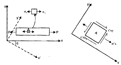
The selection of coordinate system in a given body is purely arbitrary but the stresses at a point described with respect to one coordinate system would change if the coordinate system is changed. As an example consider a rectangular plate whose thickness is small in comparison with its length and width hence it can be represented as a two-dimensional body in x-y coordinates in below diagram (a) and suppose its axis is along x-coordinate. The plate is loaded by an axial load P. In such case any point A on any transverse section will be subjected to direct tensile stress sx as shown in diagram. But if the plane passing throughout point A is oblique to which x'-axis is normal, or in other words, if the axes of reference are rotated in clockwise direction throughout an angle q to occupy new positions as x', y', the state of stress at point A will change to one shown in below diagram (b). The normal stress sx, will be given by eqn 5 and shearing stress t'xyby eqn 6. This may be noted that the shearing stress on plane normal to x' calculated by eqn 6 is accompanied by complementary shear stress on face normal to y'-axis.