Voltage Vector Diagram:
Resonance condition is obtained while XL = XC in the series circuit (it is obtained by either dropping the supply frequency while XL would decrease and XC would enhance or by enhancing the supply frequency making XL to enhance and XC to decrease).
When XL = XC, Z = R + jO = R
Also,
I0 = V/ Z = V/ R Amp [I0 = Current at resonance]
The p.f. (power factor) of the circuit becomes
cos φ = R/ Z = R/ R = 1
The expression of frequency of resonance may be obtained as follows :
Let ω0 or f0 be the frequency at which XL = XC.
i.e.
ω0 L = ωo C
or (ωo )2 = 1/ LC i.e. ωo = 1/√(LC) rad/ sec
i.e. f0 = 1 /2π √( LC) Hz
Voltage vector diagram at resonance is illustrated in Figure.
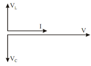
Figure: Voltage Vector Diagram at Resonance (VL = Vc)