The potentiometer
All of the resistors mentioned here are having fixed value. It is almost impossible to change or adjust their resistances. Obviously, their values will change if they overheat, or if you chip out pieces of them, but they are meant to provide an unchanging opposition to the flow of electric current.
A variable resistor can be made by connecting a bunch of fixed resistors in series or parallel, and then switching more or fewer of them in and out. This is never done in electronic circuits because there is a better way to get a variable resistance make use of potentiometer.
The construction of a potentiometer is shown in simplified form in Figure given below. A resistive strip is bent into a almost complete circle, and terminals are connected to both the ends. This generates a fixed resistance. To obtain the variable resistance, a sliding contact is attached to the rotatable shaft and bearing, and is connected to a 3rd terminal. The resistance between this middle terminal, and both of the end terminals, can vary from zero up to resistance of whole strip.
Some of the potentiometers use a straight strip of resistive material, and the control keeps on moving up and down, or from side to side. This type of variable resistor, called as slide potentiometer, is used in the graphic equalizers, as the volume controls in some stereo amplifiers and in some other applications when the linear scale is prefered to a circular scale.
Potentiometers are designed to handle very low levels of current only, at low voltage.
Linear taper
One type of potentiometer uses a strip of resistive material the density of which is constant all the way around. This results in a linear taper. The resistance between the center terminal and either end terminal changes at the steady rate as the control shaft is turned.
Suppose a linear taper potentiometer has value from zero to 280 Ω. In most units the shaft rotates around 280 degrees, or a bit more than 3-quarters of a circle. Then the resistance between center and one end terminal will increase along with the number of degrees that the shaft is turned. The resistance between center and other end terminal will be equal to 280 minus the number of degrees shaft is turned. The resistance is the linear function of the position of shaft.
Linear taper potentiometers are frequently used in electronic test instruments and in various consumer electronic devices. A graph of resistance versus shaft displacement for a linear taper potentiometer is shown in Figure given below.
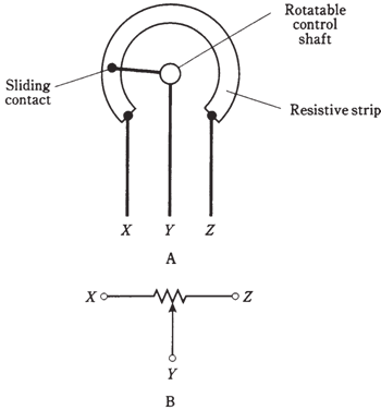
Figure-- At A, simplified drawing of the construction of a rotary potentiometer. At B, schematic symbol.
Audio or logarithmic taper
There are some applications for which linear taper potentiometers don't work well. The volume control of the radio receiver is a good example of it. Your brain perceives sound level according to logarithm of the true level of it. If you use a linear taper potentiometer as the volume control of the transistor radio or other sound system, the level will seem to go up very slowly in some parts of control range and very fast in other parts of the control range.
To compensate for the manner in which the people perceive sound level, an audio taper potentiometer is taken in use. In this device, the resistance between the center and end terminal increases in the nonlinear way. This type of potentiometer is called as logarithmic-taper device sometimes.
If the shaft is counterclockwise all the way, the volume at the speaker is zero or near zero. If you turn the shaft 30 degrees clockwise, the volume increases to some apparent level; call it one sound unit. If you turn the volume 30 degrees clockwise, the volume will seem to go up to 2 sound units. But it has actually increased much more than this, in the terms of actual sound power.
You perceive sound not as a direct function of true volume, but in units which are based on logarithm of the intensity. Audio-taper potentiometers are manufactured so that as you turn the shaft, the sound seems to increase in the natural way. The graph of resistance vs shaft displacement for the audio-taper potentiometer is shown in the Figure given below.
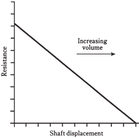
Figure-- Resistance-vs-displacement curve for linear taper potentiometer.
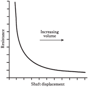
Figure- Resistance-vs-displacement curve for audio-taper potentiometer.