Voltage doubler:
By using diodes and capacitors connected in certain manners, a power supply can be used to deliver a multiple of the peak alternating current input voltage. Theoretically, large whole number multiples are possible. But you will not often see power supplies which make use of multiplication factors larger than 2.
Practically voltage multipliers are practical when load draws low current. Otherwise, regulation is poor; output voltage changes considerably with the changes in load resistance. This bugaboo becomes worse as the multiplication factor increases. This is why engineers do not attempt to make, a factor of 16 voltage multiplier. For a good high voltage power supply, it is best is to use the step up transformer, not a voltage multiplier.
A voltage-doubler circuit is shown in the figure given below. This circuit works on the whole alternating current input wave cycle, and is thus called as full-wave voltage doubler. Its direct current output voltage, when current drawn is low, is about twice the peak alternating current input voltage, or around 2.8 times the RMS alternating current input voltage.
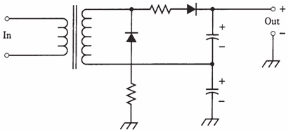
Figure-- A full-wave voltage doubler.
The operation of the voltage multiplier is dependent on ability of these capacitors to hold the charge, even when a load is connected to output of supply. Hence, the capacitors should have large values. If the intent is to get a high direct current voltage from the supply, massive capacitors will be essential.
Notice the resistors in series with diodes. These have low values, similar to those required when the diodes are connected in parallel. When supply is switched on, capacitors draw a large initial charging current. Without resistors, it would be required to use diodes with astronomical Io ratings. Else the surge current would burn them out.
This circuit subjects diodes to a PIV of 2.8 times the RMS alternating current input voltage. Thus, they should be rated for PIV of at least 4.2 times the RMS alternating current input voltage.
In this circuit, each capacitor charges to peak alternating current input voltage when there is no load (the output current is zero). As load draws current, the capacitors will have trouble staying charged to peak alternating current input voltage. This is not much of a problem as the load is light, which means, if the current is low. But, for heavy loads, output voltage will drop, and it will not be smooth direct current.
The basic difference between voltage doubler and supplies which are discussed previously, besides the increased output voltage, is the fact that the direct current output is filtered. The capacitors serve 2 purposes: to boost voltage and to filter the output. Additional filtering might be required to smooth out the direct current still more, but the circuit shown in the figure is a complete, if crude, power supply by itself.