The Hartley circuit
A method of obtaining controlled feedback at RF is shown in the figure. At point A, an NPN bipolar transistor is used; at B, an N-channel JFET is employed. The PNP and P channel circuits are similar, but the power supply is negative instead of being positive.
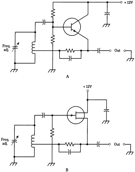
Figure-- Hartley oscillators. At point A, NPN bipolar transistor; at point B, N-channel JFET.
The circuit uses a single coil with the tap on windings to give the feedback. A variable capacitor in parallel with coil determines the oscillating frequency, and allows for the frequency adjustment. This circuit is generally called as Hartley oscillator.The Hartley oscillator uses about one quarter of its amplifier power to generate feed- back. The other 3-quarters of the power can be used as output. Oscillators do not, generally produce
more than the fraction of a watt of power. If more power is required, the signal can be boosted by one or more stages of amplification.It is important to use only the minimum amount of feedback which is necessary to get oscillation. The amount of feedback can be controlled by position of coil tap.