Ideal and Practical Voltage Sources
• An ideal voltage source that is symbolized by a model as shown in figure below is a device which generates a constant voltage across its terminals (V = E) no matter what current is drawn from it (i.e., terminal voltage is independent of load resistance linked across the terminals)
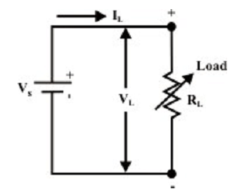
Figure: Ideal dc voltage source
For the circuit shown in figure above, the upper terminal of load is marked plus (+) and its lower terminal is marked minus (-). This point out that electrical potential of upper terminal is VL volts higher than that of lower terminal. The current flowing via the load RL is given by the expression,
VL=VS=ILRL
and we can symbolize the terminal V-I characteristic of an ideal dc voltage as a straight line parallel to the x-axis. It means that the terminal voltage VL stays constant and equivalent to the source voltage VS irrespective of the load current is small or big The V-I characteristic of ideal voltage source is symbolized in figure shown below.
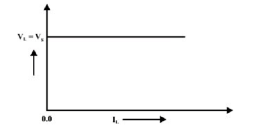
Figure: V-I characteristics of Ideal voltage source
• Though, real or practical dc voltage sources do not show these characteristics (as shown in figure above) in practice. We noted that as the load resistance RL connected across the source is reduced, the corresponding load current IL rises whereas the terminal voltage across the source reduces. We can recognize such voltage drop across the terminals with rise in load current given a resistance element (Rs) present within the voltage source. The figure shown below illustrates the model of practical or real voltage source of value Vs.
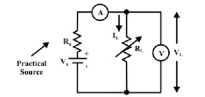
Figure: Practical dc voltage source model
The V-I characteristics terminal of the practical voltage source can be explained by an equation
VL=VS-ILRL
and this equation is symbolized graphically as shown in figure below. In practice, whenever a load resistance RL more than 100 times larger than the source resistance Rs the source can be considered around ideal voltage source. In another words, the internal resistance of the source can be omitted. Such statement can be confirmed by using the relation RL = 100 RS in equation given below.
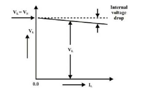
Figure: V-I characteristics of practical voltage source
Method-:
Connect a variable load resistance across the source terminals (as shown in figure Practical dc voltage source model). A voltmeter is associated across the load and an ammeter is associated in series with the load resistance. The Voltmeter and Ammeter readings for numerous choices of load resistances are symbolized on the graph paper (as shown in figure above). The slope of the line is -RS, whereas the curve intercepts with voltage axis (at IL= 0) is the value of VS.
The V-I characteristic of the source is also termed as the source’s − “regulation curve” or “load line”. The open-circuit voltage is also termed as the “no-load” voltage, VOC. The maximum permittable load current (i.e., rated current) is termed as full-load current IFl and the equivalent source or load terminal voltage is termed as “full-load” voltage VFL. We identify that the source terminal voltage differs as the load is diverse and this is due to internal voltage drop within the source. The percentage change in source terminal voltage from no-load to full-load current is known as the “voltage regulation” of the source. It is stated as
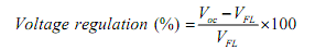
For ideal voltage source, there must be no change in terminal voltage from no-load to full-load and this equivalent to “zero voltage regulation”. For finest likely performance, the voltage source must have the lowest possible regulation and this point out a smallest possible internal voltage drop and the smallest possible internal resistance.