Temperature Detection Circuit:
Below Figure is a block diagram of a classical temperature detection circuit. That represents a balanced bridge temperature detection circuit which has been modified to eliminate the galvanometer.
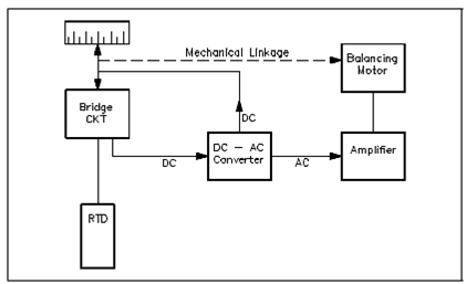
Figure: Block Diagram of a Typical Temperature Detection Circuit
The block consists of a temperature detector (RTD) which measures the temperature. The detector is felt as resistance to the bridge network. A bridge network converts this resistance to a DC voltage signal.
An electronic instrument has been established in that the DC voltage of the bridge, or the potentiometer, is converted to an AC voltage. An AC voltage is then amplified to a higher (usable) voltage which is used to drive a bi-directional motor. A bi-directional motor positions the slider on the slidewire to balance the circuit resistance.
The resistance will be infinite, and the meter will denotes an extremely high temperature if the RTD becomes open in either the unbalanced and balanced bridge circuits. If it becomes shorted, resistance will be zero, and the meter will denote a extremely low temperature.
While calibrating the circuit, a precision resistor of known value is substituted for the resistance bulb, as display in the figure.
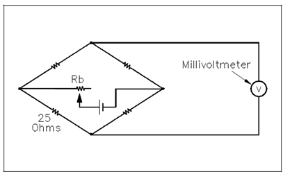
Figure Resistance Thermometer Circuit with Precision