Block Diagram of IC Timer 555 and Its Various Operating:
Modes
The block diagram of IC 555 is illustrated in Figure which may be utilized to explain its various modes of operation, as follows.
The several operating modes of the 555 timer may be explained as follows. Let + V = Vcc, - V = ground, now consider the following cases.
Case 1
When Vtr <1/3 Vcc, then C2 → High, which sets the FF resulting in V03 → HIGH.
Though, Q is low (≈ 0.2 volts for + 5 V supply) hence, Q0 is off and pin 7 behaves like an OPEN circuit.
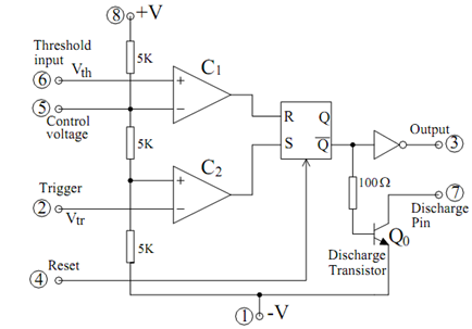
Figure: Block Diagram of IC Timer 555