Some significant components/equipments in substation
The function of a substation is to receive power at little voltage via incoming lines and transmit it at various other voltages via outgoing lines. Therefore the most significant equipment in a substation is the transformer(s). Though, for flexibility of operation and protection transformer and lines additional equipments are essential.
Assume the transformer goes out of order and the maintenance work is to be carried out. Naturally the transformer should be isolated from the incoming and also from the outgoing lines by using special kind of heavy duty (i.e., high voltage, high current) switches termed as the circuit breakers. Therefore a circuit breaker might be closed or opened physically (that is, functionally somewhat identical to switching on or off a fan or a light whenever preferred with the help of an ordinary switch in your house) in substation whenever preferred. Though unlike an ordinary switch, a circuit breaker should also operate (that is, become opened) automatically whenever a fault takes place or overloading occurs in a feeder or line. To attain this, we should have a current sensing device termed as CT (i.e., current transformer) in each line. A CT merely steps down the large current to a proportional small secondary current. Main of the CT is associated in series with the line. The 1000 A/5 A CT will step down the current by a factor of 200. Therefore when primary current occurs to be 800 A, secondary current of the CT will be 4 A.
Assume the rated current of the line is 1000 A, and due to any reason when current in the line exceeds this limit we desire to operate the circuit breaker automatically for disconnection.
In the figure shown below the fundamental scheme is presented to attain this. The secondary current of the CT is fed to the relay coil of an over current relay. Here we are not going into the constructional and operational details of an over current relay though try to tell how it functions. Based upon the strength of the current in the coil, finally an electromagnetic torque acts on an aluminum disc reserved by a spring. The spring tension is so adjusted that for normal current, the disc does not move. Though, when current exceeds the normal value, torque generated will overcome the spring tension to rotate the disc around a vertical spindle to which a long arm is attach. To the arm a copper strip is attach as shown in figure below. Therefore the arm too will move whenever the disk moves.
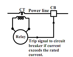
Figure: Basic scheme of protection.
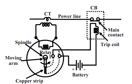
Figure: Relay and CB.
The relay has a pair of Normally opened (NO) contacts 1 & 2. Therefore, there will exist open circuit among 1 & 2 with normal current in the power line. Though, during the fault situation in the line or overloading, the arm moves in anticlockwise direction till it closes the terminals 1 & 2 with the help of the copper strip attach to the arm as described pictorially in the figure shown above. This short circuit among 1 & 2 completes a circuit including of a battery and the trip coil of the circuit breaker. The opening and closing of the major contacts of the circuit breaker based on whether its trip coil is energized or not. It is fascinating to note that trip circuit deliver is to be made separate of the A.C supply derived from the power system we desire to protect. For this reason, we suppose batteries all along with battery charger to be present in a substation.
Apart from above there will be other kinds of protective relays and different meters pointing current, voltage, power etc. To measure and point the high voltage (let say 6 kV) of the line, the voltage is stepped down to a secure value (let say 110V) by transformer termed as potential transformer (PT). Across the secondary of the PT, MI kind pointing voltmeter is associated. For illustration a voltage rating of a PT could be 6000 V/110 V. Likewise, across the secondary we can attach a low range ammeter to point the line current.