Turning Moment Diagram Assignment Help

Assignment Help: >> Flywheel - Turning Moment Diagram

Turning Moment Diagram:

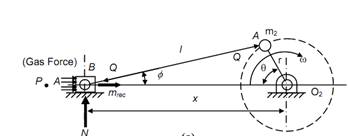
Given figure illustrated a layout of a horizontal engine.

Assume p = effective gas pressure on the piston in N/m2,

A = area of the piston in m2,

mrec = mass of reciprocating parts, that means mass of the piston gudgeon pin and part of mass of connecting rod 'm1',

Q = thrust force on the connecting rod in N, and

ω = angular velocity of the crank.     

1233_Turning Moment Diagram.png

     (a)

1402_Turning Moment Diagram1.png

      (b)                                                                         (c)

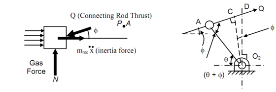
Q cos φ= p A + mrecx

727_Turning Moment Diagram2.png

2452_Turning Moment Diagram3.png

In case of a vertical engine

300_Turning Moment Diagram4.png

Also letting the correction couple, the actual turning moment is

                          M t = M + M C

Turning Moment Diagram of a Multicylinder Turning Moment Diagram of a Single Cylinder
Turning Moment Diagram of a Single Cylinder Double Acting
Free Assignment Quote

Assured A++ Grade

Get guaranteed satisfaction & time on delivery in every assignment order you paid with us! We ensure premium quality solution document along with free turntin report!

All rights reserved! Copyrights ©2019-2020 ExpertsMind IT Educational Pvt Ltd