N-channel versus P-channel
A simplified digram of an N-channel JFET, and its symbol, are shown in the Figure given below. The N-type material forms channel or path for charge carriers. In N-channel device, majority carriers are electrons. The source is at one end of channel, and the drain is at the other end. You can think of electrons being injected into the source and collected from the drain as they pass through channel. The drain is positive with respect to source.
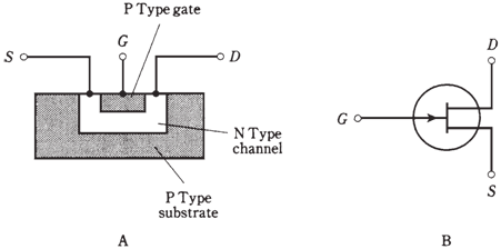
Figure:-Simplified cross-sectional drawing of an N-channel JFET and its schematic symbol.
In the N-channel device, gate consists of P-type material. Another, larger section P type material, known as substrate, forms a boundary on the side of channel opposite the gate. The JFET is formed in substrate during manufacture by the process called as diffusion.The voltage on gate produces an electric field which interferes with the flow of charge carriers through channel. The more negative EG becomes, more the electric field chokes off the current though the channel, and the ID becomes smaller.
A P-channel JFET has a channel of P-type semiconductor. The majority charge carriers are holes. The drain is negative with respect to source. The holes are injected into the source and are collected from drain. The gate and substrate are of N-type material.
In P-channel JFET, more positive EG gets, more the electric field chokes off the current through channel, and ID becomes smaller.You can recognize N-channel device by the arrow pointing inward at gate, and P-channel JFET by the arrow pointing outward. You can tell which is which (at times arrows are not included in diagrams) by the power-supply polarity. A positive drain indicates the N-channel JFET, and a negative drain indicates the P-channel type.
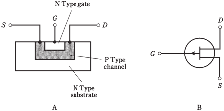
Figure--Simplified cross-sectional drawing of a P-channel JFET and its schematic symbol.
In the electronic circuits, N-channel and P-channel devices can do same type of things. The main difference is polarity of them. An N-channel device can always be replaced by a P-channel JFET, and the power-supply polarity reversed, and circuit will still work if the new device has the right specifications. Just as there are different kinds of bipolar transistors, there are different types of JFETs, each suited to some specific application. Some of the JFETs work well as weak signal amplifiers and oscillators; others are made for power amplification.
Field-effect transistors have many advantages over bipolar devices. The most important is that FETs are available which generate less internal noise than the bipolar transistors. This makes them perfect for use in the sensitive radio receivers at very high or ultra high frequencies.Field effect transistors offers high input impedances. The gate controls flow of charge carriers by the electric field, instead of an electric current.