Schematic symbols
The simplest schematic symbol is the one representing a wire or electrical conductor: a straight and solid line. At times dotted lines are used to represent conductors, but usually, dotted lines are drawn to partition diagrams into constituent circuits, or to show that certain components interact with each other or operate in step with each other. Conductor lines are always drawn horizontally across, or vertically up and down the page, so that the imaginary charge carriers are enforced to march in formation like soldiers. This makes the diagram neat and easy to read.
When two conductor lines cross, they are not connected at the crossing point unless a heavy, black dot is placed where the 2 lines meet. The dot should be clearly visible wherever the conductors are to be connected, no matter how many of them meet at junction.
A resistor is indicated by a zig-zag line. A variable resistor, or potentiometer, is in- dicated by a zig-zag line with an arrow through it, or by a zig-zag line with an arrow pointing at it. These symbols are shown in figure given below.
A cell is shown by 2 parallel lines, one longer than the other. The line which is longer shows the plus terminal. A battery, or combination of cells in the series, can be indicated by
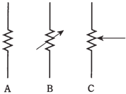
Figure:- At A, a fixed resistor. At C, a the three terminal potentiometer. At B, the two-terminal variable resistor.
4 parallel lines, long-short pattern. It is not necessary to use more than 4 lines for any battery, even though sometimes you will see 6 or eight lines. The symbols for the cell and a battery are shown in the figure which is drawn below.
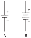
Figure--At A represent a single cell. At B there is placed a battery.
Meters are shown as circles, sometimes the circle has an arrow inside it, and the meter type, such as mA or V are written alongside the circle, as shown in the Figure given to us. Sometimes the meter type is shown in the circle, and there is no arrow present. It does not matter which manner it is done, as long as you are consistent everywhere in the schematic diagram.
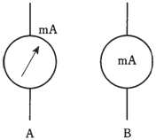
Figure: Meter symbols. At A, designator outside; at B is designated inside. Either symbol is OK.
Some other common symbols include lamp, capacitor, air-core coil, iron-core coil, chassis ground, alternating-current source, earth ground, set of terminals, and the "black box," a rectangle with the designator written inside. These are shown in given Figure drawn below
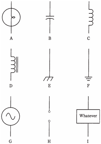
Figure:- Nine common schematic symbols. A: Incandescent lamp. B: Capacitor. C: Air-core coil. D: Iron-core coil. E: Chassis ground. F: Earth ground. G: Source of alternating current (ac). H: Pair of terminals. I: Specialized component or device.