Zener Diodes:
Diodes, which are designed for use in the breakdown region of the I-V curve, are called Zener diodes. Let us see how a Zener diode may be creates. It is possible to create the Zener breadown in diodes by direct disruption of the covalent bonds in the Si crystal with the application of high electric field of the order of 2 × 10⁷ V/m. The new hole electron pair due this disruption of the Si bond shall increase further the reverse current and Zener breakdown will occur. In other terms, with the application of adequate reverse voltage, a p-n junction shall experience a rapid avalanche breakdown and conduct current in the reverse direction. Valence electrons that break free under the affect of the applied electric field, may be accelerated enough that they can knock loose other electrons and the subsequent collisions quickly become an avalanche. While this process is taking place, very small changes in voltage may cause very large changes in current. The breakdown procedure based upon the applied electric field, so through changing the thickness of the layer to which the voltage is applied, zener diodes may be formed which break down at voltages from about 4 volts to various hundred volts.
The reverse voltage I-V characteristics of a diode by including the breakdown region are illustrated in Figure (a). As seen in the Figure, a large change in the current produces a very small change in the diode voltage in the breakdown region. These constant voltage device characteristics of Zener diodes may be utilized as a voltage regulator for varying currents in a circuit as illustrated in Figure (b). Note that for currents less than Iz0, the diode shall not behave as a Zener diode. The zener diode uses a p-n junction in reverse bias to make use of the zener effect that is a breakdown phenomenon that holds the voltage close to constant value called as the zener voltage. This is useful in zener regulators to provide a more constant voltage as illustrated in Figure (b), for improvement of regulated power supplies. Here the voltage across the resistor RL is the same with the voltage across the Zener diode. Since we know that there is little variation in the voltage across the Zener diode over largely varying current hence the voltage across load resistor RL is approximately constant with changing currents. The reciprocal slope of I-V characteristics of the Zener diode in the breakdown region (Δ Vz / Δ Iz) is called the dynamic resistance and it is mentioned by r. Ideally r = 0 and the slope is vertical. But Zener diode has values of r few ohms for practical applications. Some of the manufacturers also specify some Iz0 below which the Zener diode cannot operate.
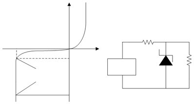
(a) (b)
Figure: (a) I-V Characteristics of a Zener Diode; and (b) A Circuit in which Zener Diode is Used as a Voltage Regulator Across a Resistor