Design of Spindle
The below Diagram illustrates schematic diagram of spindle. A spindle represents a shaft along with:
(1) Length 'a' that is acted upon by driving force F2, and
(2) Cantilever of length 'm' acted upon by external force F1.
The spindle is mainly designed for bending stiffness which needs that maximum deflection of spindle nose should not exceed a pre-specified value that is
Equation
dmax ≤ dper
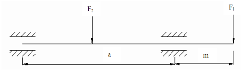
Figure: Principle of Working of Spindle
The total deflection of spindle nose contains deflection d1 of the spindle axis due to bending forces F1 and F2 and deflection d2 of the spindle axis because of compliance of the spindle supports. While the spindle has tapered hole in which a center or cutting tool is mounted, the total deflection of the center or cutting tool consists of deflections d1, d2 and d3 of the center or cutting tool because of compliance of the tapered joint.