Amplitude modulation for voice
A voice signal is complex waveform having the frequencies in range 300 Hz to 3 kHz. Direct currents are varied, or modulated, by these waveforms, therefore transmitting voice information over wires. This is how telephones in the early times worked.
Around the year 1920, when CW oscillators were developed to take place of the spar gap transmitters, engineers wondered, Can radio wave be modulated with the voice, like direct current in a telephone? If so, voices could be sent easily by wireless. Radio communications by means of Morse code was being done over thousands of miles, but CW was very slow. The idea of sending voices was quite fascinating, and engineers set about to find method to do it.
A simple amplitude modulator
An amplifier was built to have variable gain. The idea was to fluctuate the gain at voice frequency rates—to 3 kHz. Vacuum tubes were taken in the use as amplifiers back then, as solid state components have not been invented yet. But the principle of the amplitude modulation (AM) is same, whether the active devices are tubes, bipolar transistors, or FETs.
If bipolar transistors had been around in the year 1920, the 1st amplitude modulator would have resembled circuit shown in the figure given below. This circuit is a class-A RF amplifier, whose gain can be varied in the step with voice signal coupled into emitter circuit. The voice signal affects instantaneous voltage between emitter and base, varying instantaneous bias. The result is that the instantaneous RF output increases and decreases, in a way which duplicates the waveform of voice signal.
The circuit of figure given below will work well as an AM voice modulator, given that audio input is not too large. If AF is excessive, overmodulation will take place. This will result in distorted signal.
The AM transmitter
Two AM transmitters are shown in the block diagram form in the figure. At point A, modulation is done at low power level. This is low-level Amplitude modulation. All amplification stages after the modulator should be linear. That means class AB or class B must be used. If a class-C PA is used, the signal will be distorted.In some broadcast transmitters, AM is done in final PA, as shown in the figure given below. This is high-level AM. The PA operates in the class C; it is modulator as well as final amplifier. As long as PA is modulated correctly, output will be clean AM signal; RF linearity is of no concern.
The extent of modulation can be expressed as a percentage, from 0 %, representing an unmodulated carrier, to 100 %, representing full modulation. Increasing modulation past 100 %$ will cause distortion of signal, and will degrade, not enhance, effectiveness of the data transmission.In AM signal which is modulated 100 %, only 1/3 of power is used to convey the data; the other 2/3 is used by carrier wave. For this reason, AM is inefficient. There are voice modulation techniques which make better use of available transmitter power. Perhaps the widely used is single sideband (SSB), which you will learn about shortly.
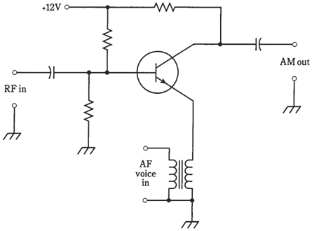
Figure--An AM modulator
Bandwidth of an AM voice signal
Suppose you could get a graphic display of an AM signal, with frequency on the horizontal axis and amplitude on vertical axis. This is actually done using an instrument called a spectrum analyzer. In the figure given here, spectral display for the AM voice radio signal at 1340 kHz is illustrated.On a spectrum analyzer, unmodulated radio carriers look like vertical lines, or pips, of heights depending on how strong they are. The carrier wave at 1340 kHz shows in the figure as a strong pip.
The horizontal scale of display in the figure given below is calibrated in increments of 1 kHz per division. This is an ideal scale for looking at an AM signal.The vertical scale is calibrated in decibels below signal level which produces 1 mW at input terminals. Every vertical division represents 3 dB. Decibels relative to 1 mW can be as abbreviated dBm by engineers. Therefore as shown in the figure, the top horizontal line is 0 dBm; the 1st line below it is − 3 dBm; the 2nd line is − 6 dBm and so on.
The audio components of voice signal show up as sidebands on either side of carrier. All of voice energy in this instance is at audio below 3 kHz. This results in sidebands within range 1340 kHz plus or minus 3 kHz, or 1337 to 1343 kHz. The frequencies in between 1337 and 1340 kHz are the lower sideband (LSB); those from
1340 to 1343 kHz is the upper sideband (USB). The bandwidth of RF signal is the difference between maximum and minimum sideband frequencies. In this case it is around 1343 to 1337 kHz, or 6 kHz.
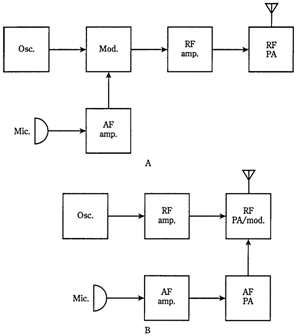
Figure--At point A, transmitter using low-level AM. At point B, a transmitter using high-level AM.
In an AM signal, the bandwidth is twice the highest audio modulating frequency. In the example of the figure given, the voice energy is all below 3 kHz, and bandwidth of complete RF signal is 6 kHz. At 3 kHz above and below the carrier, frequency cut- offs are abrupt. The transmitter makes use of an audio lowpass filter which cuts out the audio above 3 kHz. Audio receiver 3 kHz contributes nothing to intelligibility of a human voice. It is important to keep bandwidth of a signal as narrow as possible, so there will be room for various signals in given band of frequencies