NPN biasing:
You can think of the bipolar transistor as 2 diodes in reverse series. You cannot normally connect two diodes together in this manner and get a good transistor, but analogy is good for modeling behavior of bipolar transistors, such that their operation is easier to understand. A dual diode NPN transistor model is shown in the figure. The base is formed by connection of 2 diode anodes. The emitter is one of cathodes, and the collector is other.
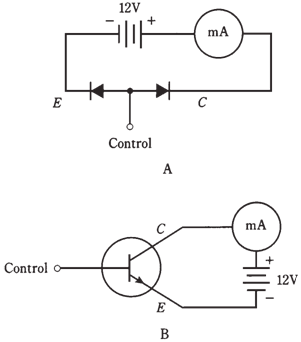
Figure-- At point A, simple NPN circuit using dual-diode modeling. At point B, the actual transistor circuit.
The normal method of biasing the NPN transistor is to have emitter negative and the collector positive. This is shown by connection of battery in the figure. Typical voltages for this battery range from 3 V to around 50 V. Most often, 6 V, 9 V, or 12 V supplies are used. The base is labeled control in figure. This is because flow of current through transistor depends critically on base bias voltage, EB, relative to emitter-collector bias voltage, EC.
Zero bias
Suppose that base is not connected to anything, or is at same potential as emitter. This is zero base bias, at times simply called as zero bias. How much current will flow through transistor? What will milliammeter (mA) show? The answer is that there will be no current in this. The meter will register zero. No current flows through the P-N junction unless forward bias is at least equal to forward breakover voltage. (For the silicon, this is around 0.6 V.) But here, forward bias is zero. Thus, the emitter base current, called simply base current and denoted IB, is zero, and the emitter-base junction does not conduct. This prevents any current from flowing between the emitter and collector, unless some signal is injected at base to change situation. This signal would have to be of positive polarity and would be required to be at least equal to forward breakover voltage of junction.
Reverse bias
Now imagine that another battery is connected to base at point marked control, such that EB is negative with respect to emitter. Will current flow through transistor?
The answer is a big no. The addition of this new battery will make the emitter-base (E-B) junction to be reverse-biased. It is assumed that the new battery is not of such a high voltage that avalanche breakdown occurs at the junction.
A signal can be injected to overcome reverse bias battery and forward breakover voltage of the E-B junction, but such type of signal would have to be of a high, positive voltage.
Forward bias
Now assume that EB is made positive, starting at the small voltages and gradually increasing. If this forward bias is less than forward breakover voltage, no current will flow. But as base voltage EB reaches the breakover, E-B junction will begin to conduct.
The base collector (B-C) junction will remain reverse-biased as long as EB is less than supply voltage (12 V in this case). In practical transistor circuits, it is common for EB to be set at the fraction of supply voltage.
Despite reverse bias of B-C junction, emitter-collector current, called as collector current and can be denoted by IC, will flow once E-B junction conducts. In the real transistor, the meter reading will jump when forward breakover voltage of E-B junction is reached. Then even a small increase in EB, attended by the rise in IB, will cause a big increase in IC. This is shown in the figure graphically.