Common-base circuit:
The common-base circuit, shown in ordinary form by the figure given below, has the base at signal ground.
The direct current bias on transistor is the same for this circuit as for common emitter circuit. The difference is that input signal is applied at the emitter, instead of at the base. This causes fluctuations in voltage across R1, causing variations in IB. The result of these small current fluctuations is the large change in the direct current through R4. Thus amplification occurs.
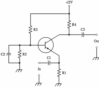
Figure: Common-base circuit configuration.
Instead of varying IB by injecting signal at base, it is being done by injecting the signal at emitter. Thus, in the common base arrangement, the output signal is in phase with input, rather than out of phase.
The signal enters through C1. Resistor R1 keeps input signal from being shorted to ground. Bias is given by R2 and R3. Capacitor C2 keeps the base at the signal ground. Resistor R4 keeps signal from being shorted out through power supply. The output we obtain is through C3. The common-base circuit gives less gain than a common emitter circuit. But it is more stable than common emitter configuration in some of the applications, especially in the radio frequency power amplifiers.