Radio-frequency amplification
The RF spectrum begins at around 9 kHz and extends upward in frequency to over 300 GHz, or 300,000,000,000 Hz. Only a sketch of the most important characteristics can be given here.
Weak-signal versus power amplifiers
Some RF amplifiers are designed for the weak-signal work. The general circuits, which were shown earlier, are representative of such amplifiers, when the capacitors have values of around 1 µF or less. Higher the frequency, smaller the values of capacitors.The front end, or 1st amplifying stage, of a radio receiver requires most sensitive possible amplifier. Sensitivity can be determined by 2 factors: gain and noise figure.
The noise figure of the amplifier is measure of how well it can amplify desired signal, without injecting the unwanted noise. All the bipolar transistors or FETs; create some white noise due to the movement of charge carriers. Generally JFETs produce less noise than the bipolar transistors. Gallium arsenide FETs, called as GaAsFETs (pronounced gasfets), are least noisy of all.Higher the frequency at which the weak signal amplifier is designed, the more important the noise figure becomes. This is because there is much less atmospheric noise at higher radio frequencies, as compared to the lower frequencies. At 1.8 MHz, for instance, the airwaves contain much atmospheric noise, and it does not make a significant difference if receiver introduces a little noise itself. But at 1.8 GHz atmospheric noise is nonexistent, and receiver performance depends critically on the amount of internally generated noise.
Weak signal amplifiers always use resonant circuits. This optimizes the amplification at desired frequency, while assisting to cut out noise on unwanted frequencies. A characteristic tuned GaAsFET weak signal RF amplifier is given in the figure below. It is designed for around 10 MHz.
Broadband PAs
At RF, a PA can be either broadband or tuned.The basic advantage of a broadband PA is ease of operation, as it does not require tuning. A broadbanded amplifier is not particular with respect to frequency within design range of it, like 1.5 MHz through 15 MHz. The operator need not worry about the critical adjustments, nor bother to change them while changing the frequency.One basic disadvantage of broadband PAs is that they are less efficient than tuned PAs. This usually is not too difficult to put up with, though, considering convenience of not fiddling with the tuning.
The more serious problem with the broadband PAs is that they will amplify anything in design range, whether you want it to go over the air or not. If some earlier stage in the transmitter is oscillating at a frequency nowhere near intended signal frequency, and
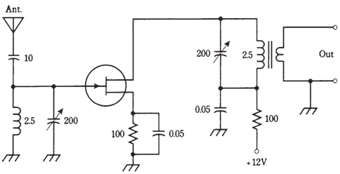
Figure-- A tuned RF amplifier for use at about 10 MHz. Resistances are in ohms.Capacitances are in F if less than 1, and in pF if over 1. Inductances are in µH.
if this undesired signal falls within design frequency range of PA broadband, it will be amplified. The result will be unintended RF emission from radio transmitter. Such unwanted signals are known as spurious emissions, and they happen more often than you might even think.
A typical broadband PA circuit is diagrammed schematically. The NPN bipolar transistor is a power transistor. It will provide around 3 W of continuous RF output from 1.5 MHz by 15 MHz. The transformers are a critical part of the circuit; they should be designed to work well over the 10:1 range of frequencies. This circuit is appropriate for use on the ham radio bands at 160, 80, 75, 40, 30, and 20 meters.
Tuned PAs
The tuned RF power amplifier provides improved efficiency compared with the broadband designs. Also, tuning helps to reduce the chances of fake signals being amplified and transmitted over air.
The other advantage of tuned PAs is that they can work into the wide range of load impedances. In addition to this a tuning control, or resonant circuit which adjusts the output of amplifier to operating frequency, there is a loading control which optimizes the signal transfer between amplifier and the load (normally an antenna).
The major drawback of a tuned PA is which the adjustment takes time, and improper adjustment can result in damage to amplifying device (bipolar transistor or FET). If tuning and loading controls are out of kilter, efficiency of the amplifier will be extremely low sometimes practically zero while the direct current collector or drain power input is very high. Solid state devices overheat very quickly under these conditions.
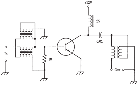
Figure--A broadband RF power amplifier, capable of producing few watts output.
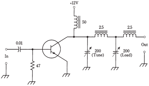
Figure--A tuned RF power amplifier, capable of producing a few watts output.
A tuned RF PA, giving 3 W output at 10 MHz or so, is shown in the Figure given below. The transistor is the same as for broadband amplifier which is discussed above. The tuning and loading controls must be adjusted for maximum RF power output as indicated on the wattmeter in the feed line going to load.