The three prototyping methods used are:
a) RapidPrototyping: This is used to model the pins (large 1, 2 and small), lock disk and crank.
b) CNCMachining: Used for the Link.
c) Laser Cutting: Geneva Wheel
The following figure shows how a Geneva Wheel would look like,
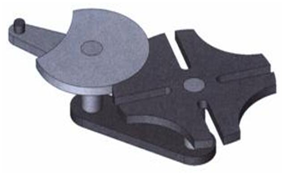
Some preliminary drawings are drawn using the Solid works software, which are used to model the parts for the Geneva wheel. The following figures show the preliminarydrawings usedtobuildthethreedimensionalpart withSW.
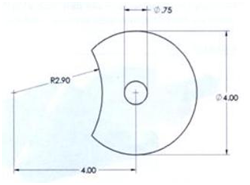
Lock Disk
The automation techniques and applications are discussed. The teachers were asked about their view of automation applications. They came up with different answers like the automation is used in ATM's, Clean rooms, Automobile assembly plants. Later there is an introduction to PLC (Programmable Logic Controller). Programmable controllers are generally programmed in ladder diagram or 'relay diagram' which is nothing but a symbolic representation of electric circuits.
There are several languages designed for user communication with a PLC, among which ladder diagram is the most popular. Ladder diagram consists of one vertical line found on the left hand side, and lines which branch off to the right. Line on the left is called a "bus bar", and lines that branch off to the right are instruction lines. Conditions which lead to instructions positioned at the right edge of a diagram are stored along instruction lines. Logical combination of these conditions determineswhen and in what way instruction on the right will execute. Basic elements of a relay diagram can be seen in the following picture.
Most instructions require at least one operand, and often more than one. Operand can be some memory location, one memory location bit, or some numeric value -number.In a case when we wish to proclaim a constant as an operand, designation # is used beneath the numeric writing (for a compiler to know it is a constant and not an address). A ladder diagram consists of two basic parts: left section also called conditional, and a right section which has instructions. When a condition is fulfilled, instruction is executed.
The picture shown above represents an example of a ladder diagram where relay is activated in PLC controller when signal appears at input line 0. Vertical line pairs are called conditions. Each condition in a ladder diagram has a value ON or OFF, depending on a bit status assigned to it. In this case, this bit is also physically present as an input line (screw terminal) to a PLC controller. If a key is attached to a corresponding screw terminal, you can change bit status from a logic one status to logic zero status, and vice versa. Status of logic one is usually designated as ON, and status of logic zero as OFF
The right section of a ladder diagram is an instruction which is executed if left condition is fulfilled. There are several types of instructions that could easily be divided into simple and complex. Example of a simple instruction is activation of some bit in memory location. In the example above, this bit has physical connotation because it is connected with a relay inside a PLC controller. When a CPU activates one of the leading four bits 10, relay contacts move and connect lines attached to it. In this case, these are the lines connected to a screw terminal marked as 0 and to one of COM screw terminals.
When programming with a ladder diagram, logical combination of ON and OFF conditions set before the instruction determines the eventual condition under which the instruction will be, or will not be executed. This condition, which can have only ON or OFF values is called instruction execution condition. Operand assigned to any instruction in a relay diagram can be any bit. This means that conditions in a relay diagram can be determined by a status of I/O bits, operational bits, timers/counters, etc. Concepts normally open and normally closed contact ought to be clarified and explained in detail in the example of a PLC controller input and output. The easiest way to explain them is in the example of a relay.
Normally open contacts would represent relay contacts that would perform a connection upon receipt of a signal. Unlike open contacts, with normally closed contacts signal will interrupt a contact, or turn a relay off. Previous picture shows what this looks like in practice. First two relays are defined as normally open , and the other two as normally closed. All relays react to a signal! First relay (10) has a signal and closes its contacts. Second relay (11) does not have a signal and remains opened. Third relay (12) has a signal and opens its contacts considering it is defined as a closed contact. Fourth relay (13) does not have a signal and remains closed because it is so defined.
Concepts normally open and normally closed contact ought to be clarified and explained in detail in the example of a PLC controller input and output. The easiest way to explain them is in the example of a relay.
If input is defined as an input with normally closed contact, pushing the key will interrupt instruction found after the condition. In this case, this will cause deactivation of relay 0 (relay is active until the key is pressed). You can see in picture below how keys are connected, and view the relay diagrams in both cases.
Normally open/closed conditions differ in a ladder diagram by a diagonal line across a symbol. What determines an execution condition for instruction is a bit status marked beneath each condition on instruction line. Normally open condition is ON if its operand bit has ON status, or its status is OFF if that is the status of its operand bit. Normally closed condition is ON when its operand bit is OFF, or it has OFF status when the status of its operand bit is ON.
Each of them is provided with a PLC kit. The components of PLC (I/O system, CPU, power supply) are shown practically. I/O modules (16 I/O and 32 I/O) are shown. Programming with PLC is done using ladder logic. Simple programs like to turn on the LED are shown. Now the teachers with the help Direct SOFT5 has done the programming and linked up to the PLC kit with the Ethernet cable.
Later there was a presentation about Industrial Robots. Topics like what is an industrial robot? , basic robots are discussed. Demonstration of robots is done and the instructor helped in about how to write programs for robot.